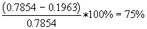
(This article was sent to me by Wim after a "discussion" on Andy's (now defunct) Q&A about what consequences the dreaded skin effect may pose in audio applications. Please note, some of this information was taken from other sources, and some of these images may have been used without permission by the author - Cameron). Skin effect is a physical phenomenon that relates to the limited penetration into a conductor of an RadioFrequent signal according to its frequency. All electric currents generate magnetic fields that in turn can affect the current (this is the principle behind electric guitar pickups or electrical motors). In a direct current case everything is constant and so nothing seems to happen. With an alternating current, however, there is a delay in the magnetic field's response to the change in current and the 'old' magnetic field tends to push the current towards the outside of the conductor. As the frequency increases, so does the effect until at very high frequencies the entire current flows in a very narrow skin on the conductor--hence the name. An increase in frequency causes non-uniform current density and an increased AC resistance of the wire. Coax uses this effect to keep the RadioFrequent signal inside and any coupled outside interference on its shield's outside surface. This begins to fall apart as the frequency is lowered and the penetration, which is a gradient, begins to mix the shield's outside interference energy with the desired inside energy, A ground loop, which imparts 60 Hz onto a desired signal, is due to dissimilar grounds causing ac current flow between points via the coax shield. A serious effect of the skin effect is the virtually decreasing cross-section area of the cable which is conducting the current: assume a cable with a diameter of 1 square inch. This cable has a cross section of
A : the cross section in square inches P : 3.141593 d : the diameter of the cable This results in a cross section of 0.7854 inches. Now, imagine that due to the skin effect, at a certain frequency, we lose the inner half of the cable:
Now the total current has to flow in a section that is reduced by
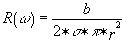
Taking an exact diameter wherein no current flows is a very simplified calculation that will do in most cases, but the exact impedance calculation can be done with the next formulas :
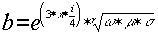
with : R(w ) : the AC resistance as a function of the frequency w : 2*P *f f : the frequency in Hz r : the wire radius in meter s : the sheet resistivity (W /square) of the material at DC
with :
The AC resistance as a function of the frequency can also be calculated with the following formula :
with : r : the wire radius in meter R(w ) : the AC resistance as a function of the frequency R(DC) : the DC resistance of the wire
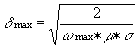
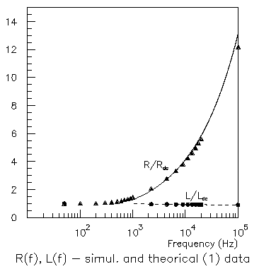
w max : 2*P *fmax m : permeability of air (4*P *10-7) H.m H : Henry (unit to measure magnetic field density) s : the sheet resistivity (W /square) of the material at DC This picture shows the relative change in resistance at different frequencies for a single wire.
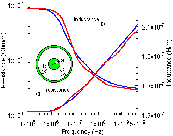
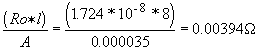
The same, but now for a coaxial wire. So when omega (w ) is very high at high frequencies ( These conductors have more surface area while using less amount of material so they are cheaper and lighter. Litze-wire is constructed just the same as the special caraudio power wire, except the fact that every single strand is isolated from the others by furnishing it. In this way, the current can use all the many little surfaces of all the brands separate, which give much more surface area than when using the one (big) surface of the entire cable. Litze-wire is distinguishable from the ordinary cable by heating it with a flame or soldering iron: the furnish will start scorching and smelling. Now we come to the interesting part : calculating the cable’s resistance and the voltage drop in it. Every metal (superconductors aren’t made from metal) on earth has a characteristic resistance. The metal with the best conductance is silver, followed directly by copper. Because silver is way too expensive, mostly copper (sometimes aluminum) is used. The characteristic resistance of copper is the following : Ro=1.724*10-8 (in Ohms/m) So, a solid bar copper with an effective cross section "A" of 1 square cm (0.155 square inches; one inch=2.54 cm) and a length "l" of 1 m (39.4 inches) has a resistance of 1.724*10-4 ohm at 20 degrees Celsius. (68 degrees Fahrenheit : Tfarenheit=32+9/5 Tcelsius) Increasing the temperature will also increase the characteristic resistance, but this effect is negligible (0.39% per degree Celsius). Decreasing the effective (remember the skin-effect!) cross section area will lead to a increasing resistance, just like taking a longer length will. Now when we got a system with a 35 square mm (0.0543 square inches ; I don’t know the "Gauge" system) and a length of 8 m (315 inch) we get a resistance of :
Now, when we get an one channel amp that gives out 100 W RMS at 12 volt (It doesn’t matter if this is in 4,2 or one ohm; it’s just the amount of output power). Let us now assume that the amplifier section itself has 75% efficiency and the power supply unit has 80% efficiency. So this gives a 60% overall efficiency. Now for delivering 100 W, the amp has to consume 100/0.60=167 Watt. 167 W at 12V gives 167/12=14A. Now, we can calculate the voltage drop in the power cable : 14 A * 0.003886 ohm = 0.0544 Volt. This also gives us a powerful tool to calculate the system’s power consumption (NOT the RMS speaker output!!! since we don’t know the efficiency of the amplifier). Measure the cable’s voltage drop and divide this by the calculated resistance. This gives the total drained current. Multiply this by the battery voltage and you get the total consumed power of your system. Now what about stuff like multi-strand or oxygen free cable? I can’t prove that there’s no difference at all between them and ordinary industrial wire, but I’m 99.99% sure that there’s no electrical difference concerning power and speaker wire. Every decent amp has sufficient power supply ripple rejection (alternator whine on the +12V wire) to suppress power irregularities. Irregularities on the ground wire (caused by a bad ground connection) can’t be suppressed because they enter the amp via the signal wire and the amp can’t distinguish signal from alternator whine. So if you hear this, it’s the ground wire, probably not the power wire. Besides if you have a capacitor, it shortens unwanted signals to ground, so that you get a pure DC at you amp’s terminals whatever kind of cable you use. Only the DC voltage will be higher if you use a cable with more cross section, so you can get more power from you amp. The only difference fancy wire makes, is that it’s looking nice (for competing). So we can conclude that if the strands of a cable are NOT separately isolated , it’s totally useless to use special fine stranded wire. The skin effect is totally negligible at frequencies lower then 50Khz and a car system is powered with DC, so in a car you don’t have to fear the skin effect. Even the ultra high frequencies of the tweeter wires aren’t high enough to have an audible effect. Otherwise than power and speaker wire, there can be a major difference concerning SIGNAL wire. This is all the wire between your head unit’s output and the amp’s input. In general the lower the signal amplitude, the more care you should take at it. That’s because these wires are conducting a very low power signal. A 0.1 V noise signal can easily mutilate a 1V music signal so that you get a very poor signal to noise ratio of 20 dB. When this same 0.1V noise signal happens at the output of a 100 W RMS power amp, you can hear it much harder : 100W RMS@4 ohm gives 20 V RMS at the speaker terminal. This gives a signal to noise ratio of 46 dB.
Also, any noise or interference picked up in the signal wires will be amplified. Use good quality wire with an adequate shielding. I can’t give a good brand, but most of the top quality brands will also produce good wire to connect their stuff. Make good interconnections and keep them as far away from the power wires as possible. Here is another associated article link - Speaker Cables: Science or Snake Oil by Nelson Pass from Speaker Builder, 2/1980. |